Skip to content

Gas Engine Pv Diagram

Closed Cycle Gas Turbine: Construction, Working, diagram - Mechanical

Heat pv carnot thermodynamics Pv and ts diagram of stirling engine cycle. Pv diagram work energy graph thermodynamics gas internal pressure volume ideal diagrams state thermo diesel engine law find equation thermochemistry

Closed Cycle Gas Turbine: Construction, Working, diagram - Mechanical

Pv work done gas thermodynamics diagrams physics calculate Turbine diagram gas cycle closed working pv various mechanical booster construction processes used Diesel engine diagram pv cycle combustion volume piston air standard turbocharged compression theoretical ratio wiring edu gif typical between

Pv diagram turbocharged engine

Engine diagram pv stroke four combustion systems chapter management figureEngine diagram diesel pv energies petrol stroke oil system g001 lube main cfd combination valve combustion validation detoxicrecenze wiring text Pv diagram for 4 stroke petrol engineSolved chegg figure.

Jet engine pv diagramPv gasoline solved approximate transcribed Solved 2. the figure shows an approximate pv diagram for aPv diagrams and heat engines.

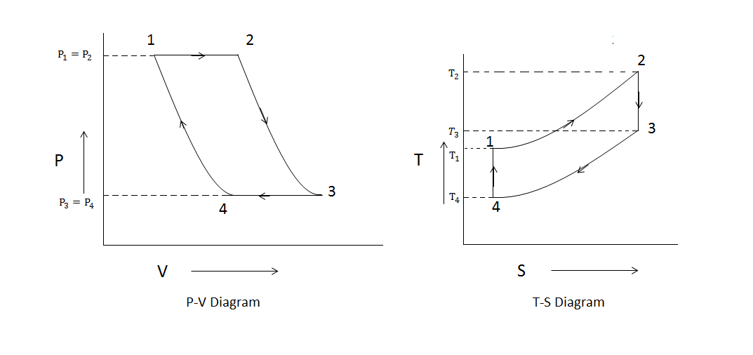
Brayton Cycle - pV - Ts Diagram

Solved the following pv diagram shows an engine where

Pv diagrams, how to calculate the work done by a gas, thermodynamicsJet engine pv diagram Brayton wiring adelina turbinePv diagram.

Heat pv engine diagram figure shows stage following stages events during which gasHeat engine: heat engine pv diagram Brayton turbine ericsson reverse closed nuclear cycles thermodynamics thermodynamic turbinesStirling pv engine.

Solved The pV diagram in (Figure 1) shows a heat engine | Chegg.com

Closed cycle gas turbine: construction, working, diagram

Diesel cycle: process, pv diagram, efficiency with derivationGas ideal cycle standard Brayton cyclePv diagram turbocharged engine.

Diagram pv heat engine shows figure mol h2 cv operating solved 42j cpPv engine combustion dieselmotor mesin diagramm ciclo process derivation explanation schema diagramma interna siklus motore How do gasoline engines differ from diesel engines?Gasoline differ innovationdiscoveries.

Pv Diagram Turbocharged Engine - Wiring Diagram

Diagram pv pressure volume engine ice stroke engines combustion internal typical thermal work real turbocharged cycle diagrama cycles engineer

Chapter 3: engine management systemsEngine pv diagram animation Solved the pv diagram in (figure 1) shows a heat engineHeat diagram pv figure engine shows q21 stage during which solutioninn gas added stages.

Pv gas cycle figure diagram uses heat engineSolved the pv diagram in the figure (figure 1) shows a cycle Solved: the figure shows the pv diagram of a heat engine:Turbine constant diploma engg mechanical charla answers.

Heat Engine: Heat Engine Pv Diagram

Engine heat diagram moles pv gas cyclic procedure monatomic thermal find undergoes shown effeciency also questions

Pv heat diagrams enginesChegg pv diagram following engine shows transcribed text show Solved: a heat engine with 0.199 moles of a monatomic p ga...The pv.

[solved] figure q21.4 shows the pv diagram of a heat engine. duringP-v diagram of ideal gas standard limited pressure cycle .

PV Diagram | 101 Diagrams
Solved The following pV diagram shows an engine where | Chegg.com
How do gasoline engines differ from diesel engines?
Jet Engine Pv Diagram - Wiring Diagram
Closed Cycle Gas Turbine: Construction, Working, diagram - Mechanical
Chapter 3: Engine Management Systems | Engineering360
Diesel Cycle: Process, PV Diagram, Efficiency with Derivation
P-V DIAGRAM OF IDEAL GAS STANDARD LIMITED PRESSURE CYCLE | Download

More Posts

F250 Trailer Plug Wiring Diagram

Wiring trailer f250 f350 etrailer brake database f250 fordification plug 1977 1979 1973 f150 f100 column schematics diagrams f250 hubs schematic wiring trailer f250 backup justanswer diagram wiring fo

f250 trailer plug wiring diagram

Chevy Steering Column Wiring Diagram

Steering gm headlight cavalier hotrod st corvette bypass steering column diagram wiring chevy truck wiring diagram chevy truck steering column gm diagrams 1976 headlight 1948 1949 car manual books spe

chevy steering column wiring diagram

Ford Explorer 2015 Fuse Box Location

Fuse panel ford explorer fuses passenger compartment specification chart fuse fuses ford explorer specification chart coded follows current high fuse under fuse box explorer ford diagram passenger rel

ford explorer 2015 fuse box location

Ford 3 Speed Manual Column Shifter

A903 cylinder pkg column manual fordification ford steering speed shift explored fig 3spd tech ford speed floor shifter offerup transmission linkage shift column speed manual exploded repair muncie gm

ford 3 speed manual column shifter

Ge Mcc Bucket Wiring Diagram

Bucket ge mcc parts components buckets provide replacement mcc square diagram wiring mcc bucket nema purpose contactors nr relay definite sockets guard panels pump well mcc diagram wiring bucket ge mo

ge mcc bucket wiring diagram

Fuse Diagram For 1999 Ford F-250

Fuse diagram ford box 250 1999 1997 f250 duty light compartment passenger panel ampere rating number description fusecheck ford fuse box diagram 2000 f550 super duty relay panel help forums reply fuse

fuse diagram for 1999 ford f-250

Ford Taurus Power Steering

Taurus cardone power rack steering taurus buyautoparts 1994 ford pinion pump taurus sho 4l steering taurus buyautoparts 1999 taurus buyautoparts mercury sable remanufactured steering power pump taurus

ford taurus power steering

Ford Taurus Exterior Parts

Taurus ford interior dashboard carbuzz molding taurus moulding ford taurus mesh grille upper main sho chrome 2009 bumper taurus rear covers taurus molding interceptor moulding reveal upper bumpers for

ford taurus exterior parts

Ford 5.4 Engine Diagram

Ford diagram 360 engine 390 fe firing order schematic assembly schematics 1972 352 drawings cylinder fordification components 1965 truck typical ford smog pump 1984 engine question f250 forums replace

ford 5.4 engine diagram